FEA Analysis of Components in Leak Testing Machine
- February 23, 2018
- Posted by: RSIS
- Categories: Engineering, Industrial & Systems Engineering, Industrial Engineering
International Journal of Research and Innovation in Applied Science (IJRIAS) | Volume III, Issue I, January 2018 | ISSN 2454-6194
FEA Analysis of Components in Leak Testing Machine
Ramprasad Shetti#, Mayur Appaiah*

*Asst. Professor
#, * Department of Industrial Engineering & Management,
B.M.S. College of Engineering, VTU PG Extension Centre, Bangalore-560019, Karnataka, India
Abstract- This paper is regarding the design of the leak testing machine which can test 4 filters at a time which is connected to the Cylinder activation. After the machine is designed various issues are addressed which occurred during testing of the machine.
Keywords -Leak Testing, Prototyping, Activation, Linear motion, Clamping.
I. INRODUCTION
Leak test machine is predominantly used by the filter manufacturing industries for end of line leakage testing of multiple filters to be tested at a given time, It checks for common defects in leak tests they are voids, pores, weld failure and goodness of fit. FEA tools were used to predict the maximum loads during service condition
The Leak testing machines consists of the below parts
1. Hinge mechanism
2. Plunger
3. Rod Guide
4. Floating Plug
5. Bushing
6. Frame
7. Tank
8. Cover
9. Installation Board.
10. Control Panel box
The leak Testing machine schematic is as shown in Fig 1. The compressed air enters into the set up and it should not show the bubble for 20 sec.
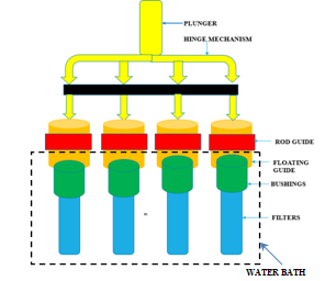
Fig 1: Single Station Leak testing machine
A. CFD analysis done on the pipe:
The CFD analysis on the pipe showed uniform flow, no supersonic flow was observed
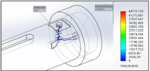
Fig 2: CFD analysis of the pipe
Load analysis on the system was done and was analyzed for the above mechanism, all the load is getting transferred to the bushings and as result proper clamping of the filter with the bushing do not take place.
Load analysis on the system was done and was analyzed for the above mechanism, all the load is getting transferred to the bushings and as result proper clamping of the filter with the bushing do not take place.
Initially the team had decided to go for a brass bushing, but brass has is slippery in nature due to its sticky characteristics.
Also below analysis was done on bushing changing the material of the bushing.
